
Simplified diagram
AIRBAG LIGHT FIX
for 1999 Chevy
Silverado/GMC Sierra
- These instructions were originally written by a Chevy trucks forums member, Shawn Lin in April 23, 2004. Some years back I wanted to do this same mod and was able to get in touch with him. He fortunatley still had the instructions and graciously sent them to me. Since this seems to be nowhere to be found on the web anymore I'm rehosting them in case anyone wants to do this. I put an Escalade cluster in my 99 GMC several years ago and used this mod and it has worked perfectly ever since. - Rich (MixManSC)
Problem: You bought an expensive new 2000-02 Escalade or Denali instrument cluster, put it in your 1999 truck, and the airbag light stays on! DOH! The reason is because the 1999 trucks use an earlier SDM (airbag computer) that grounds pin A11 on the cluster to turn on the airbag light, and open circuit to turn off the airbag light. In the 2000-02 trucks, pin A11 is not used because the SDM sends a command on the Class 2 Serial Data Bus telling the cluster to turn off the light.
Solution: To make my 2001 GMC Yukon Denali cluster's airbag light work properly in my 1999 Chevrolet Silverado, I decided to rewire the cluster so that the SDM (airbag computer) can control the airbag light directly as it does in a 1999 cluster. This required only an NPN transistor, 2 10k ohm resistors, and a little soldering. I was able to find all 3 parts in my junk bin, so total cost of the project was $0.
Technical Details: Most people will probably want to skip over the
technical stuff, but here it is anyway.
The airbag light is
a high-brightness red LED which is connected to a positive voltage feed at
all times. A logic circuit grounds the LED's negative feed when it wants to
turn on the LED. In a 1999 truck, this logic will keep the LED's negative feed
grounded, so the LED negative feed needs to be disconnected by disconnecting
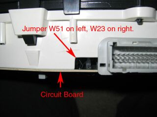
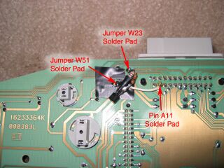
jumper wire W51. The SDM grounds pin A11 in the 1999 clusters to turn on the
LED. However, the SDM also keeps the A11 pin grounded when the truck is off, so
if pin A11 were directly connected to the negative pin of the LED, the LED would
be lit constantly when the truck is off. A solution to this is to use an NPN
transistor. The NPN transistor in this application works as a switch. The
Emitter is connected to pin A11, the Collector to the negative of the LED, and
Base is connected to +12V switched (wire jumper W23). When the ignition is
turned on, the Base gets a positive charge which allows current to flow from the
Emitter to Collector. If the Base sees 0V, the transistor is OFF so the LED will
remain OFF. This takes care of the problem of the LED staying on even when
ignition is off. When the ignition is on, the transistor is energized so the SDM
can control the LED as it normally does. Two resistors are required in this
circuit, a 10k ohm resistor is placed inline between the transistor Base and the
switched +12V to reduce base current (this protects the transistor). A 10k ohm
resistor is placed across the switched +12V and the Emitter. It acts as a
pull-up resistor that pulls pin A11 high when the SDM turns off the LED. The
pull-up resistor is required because without it, some leakage current from the
SDM keeps the airbag light on very dimly when it is "off".
|
|
Simplified diagram |
Required Parts and Materials
Instructions
WARNING: Attempting this instrument cluster mod could potentially damage it! If anything goes wrong, it's not my fault! Proceed at your own risk.
 |
|
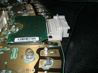
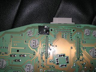
Small space next to
connector |
 |
 |
|
I insulated it with electrical tape just
in case. |
You can see both jumpers from this
top-view pic |
 |
|
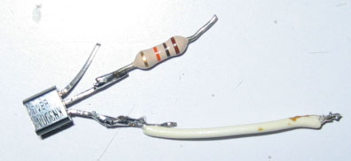
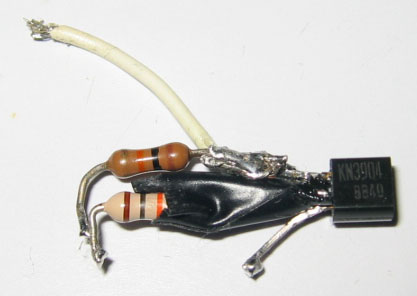
Resistor and Wire soldered to
transistor. |
 |
|
Both resistors soldered on, pin B
insulated. |
 |
|
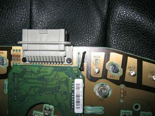
I insulated the circuit board just in
case. |
 |
|
Soldered to the circuit
board. |
I'm not an electronics engineer, just a nerdy computer programmer that likes playing with electronics, so there may be better ways to design this circuit. I'm also not a particularly good writer.